A vacuum gauge can show adequate pressure while a workpiece still drops during acceleration. The leak may be at the lip, fitting, hose, valve, or porous surface; the cup may also be too stiff, misaligned, undersized for the motion, or unable to follow curvature. Reliable suction cup troubleshooting separates seal formation from the dynamic holding requirement.
This guide gives automation teams a sequence for diagnosing suction cup grip loss without treating increased vacuum as the only correction.
Table of Contents
Document the Suction Cup Failure Point
Record whether pickup fails on approach, during lift, acceleration, rotation, dwell, or release. Note workpiece lot, surface, temperature, contamination, cycle time, vacuum level, and robot motion. A suction cup that holds at rest but fails during acceleration has a different problem from one that never seals.
Capture slow-motion video and vacuum-time traces when available. Mark cup positions in a multi-cup array.
Test the Vacuum Circuit for Leakage
Isolate the generator, valve, hose, fitting, mounting thread, and cup using the equipment procedure. Check response and decay rather than one steady gauge reading. Small hose restrictions can delay evacuation even when final vacuum is adequate. The suction cup may release before the sensor threshold is reached.
Inspect cracked hose, loose threads, blocked filters, and valve timing. Increasing generator capacity does not repair a leak.
| Symptom | Priority check | Possible direction |
|---|---|---|
| Never forms seal | Lip, alignment, surface porosity | Change approach or cup style |
| Drops on acceleration | Dynamic load and array distribution | Reduce motion or increase effective area |
| Slow evacuation | Restriction or volume | Hose, valve, generator review |
| One cup fails repeatedly | Local surface or mount variation | Map alignment and lip condition |
| Grip worsens when hot | Material and surface change | Temperature-compatible compound |
Match Lip Geometry to the Workpiece
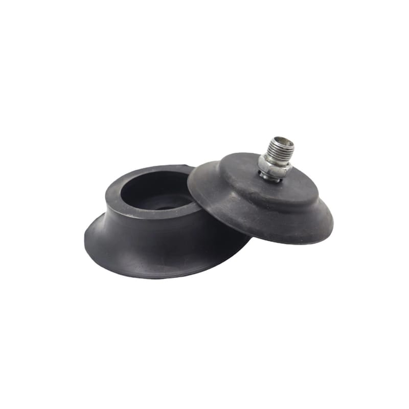
Flat cups suit relatively flat, smooth surfaces. Bellows can accommodate height variation and curvature but may move laterally under acceleration. Thin lips conform to texture yet may wear or fold. Select suction cup shape from surface geometry, porosity, roughness, and permitted marks.
Test representative production parts, including worst-case curvature, texture, oil, dust, and seams.
Align the Approach and Provide Compliance
The cup should approach near normal to the local surface unless the design intentionally handles angle. A compliant mount can absorb small position error, but too much freedom allows swing. Set stroke so the suction cup compresses enough to seal without collapsing or wrinkling.
Protect the lip from sharp edges and ensure the center support does not contact the workpiece prematurely.
- Map failure timing.
- Leak-test each circuit segment.
- Check suction cup alignment and stroke.
- Use real worst-case workpieces.
- Include acceleration and emergency motion in validation.
Calculate Dynamic Holding Demand
Holding force is affected by effective sealed area and pressure differential, then reduced by leakage, cup deformation, load distribution, acceleration, orientation, and safety requirements. Use the responsible machine-design method and include robot motion, not just workpiece weight. A suction cup array may share load unevenly.
Center of gravity and cup spacing create moments. One local seal loss can overload remaining cups.
Inspect Lip Wear and Contamination
Look for nicks, flattening, hardening, swelling, embedded particles, and molded defects. Clean using a compatible method. A damaged suction cup lip cannot be rescued by higher vacuum, and aggressive solvent may create another problem.
Track cycles and failure location without claiming a universal replacement interval.
Match Rubber to Temperature and Fluids
NBR, silicone, and other compounds offer different temperature, oil, wear, marking, and flexibility behavior. Use ASTM D471, ASTM D573, ASTM D2240, and ASTM D395 where relevant.
The exact suction cup compound must be tested with workpiece fluids, cleaners, and temperature.
Validate the Complete Pick-and-Place Cycle
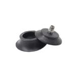
Run worst-case parts through pickup, evacuation, lift, acceleration, rotation, dwell, placement, and release. Record vacuum at each cup or zone, slip, marks, dropped-part detection, and recovery. The threaded rubber suction cup, rubber suction cup application guide, and rubber material selection guide provide related cup and rubber guidance.
Approve the suction cup only with the production motion and circuit configuration.
Sensor placement and thresholds influence apparent reliability. A sensor near the generator may not detect a leak at one remote cup quickly enough, while a shared circuit can mask a failed position. Decide whether zones or individual cups need monitoring based on dropped-part risk. Validate response time during pickup and a controlled leak without defeating safety functions.
Hose routing should avoid sharp bends, pinching, excessive length, and motion that pulls the cup off-angle. Robot dress packs can change the load on a mount throughout the path. Observe the complete cycle and check fittings at both motion extremes. A compliant mounting element should absorb position error without becoming an uncontrolled pendulum.
For porous workpieces, flow capacity may matter more than high ultimate vacuum. Test the worst production porosity and surface contamination, then choose generator, reservoir, valves, and cup area as a system. Do not seal a porous sample artificially during approval unless that condition also exists in production.
Release behavior needs validation as carefully as pickup. A cup can stick, invert, or release slowly when the workpiece is oily, hot, highly smooth, or compliant. Confirm blow-off pressure and timing within equipment limits, and make sure the released part does not rebound into the lip. Observe whether residual vacuum in a long line delays placement.
In an array, manifold layout can give positions different evacuation times. Equal hose length is not always required, but each branch should meet the timing and leak-detection objective. Isolate or zone positions when one porous surface could consume flow needed by the others. Record which positions support moments during acceleration and whether a failed cup can overload its neighbors.
Replacement parts should preserve lip profile, compound, thread, insert alignment, and free height, not merely outside diameter. Verify samples on the production workpiece and mounting hardware. A small change in stroke or center support can alter sealing even when the replacement fits the bracket.
Frequently Asked Questions
Why does a suction cup hold at rest but drop in motion?
Acceleration, moments, uneven load sharing, lateral compliance, delayed vacuum, or local leakage may exceed dynamic holding capacity.
Does higher vacuum always improve suction cup grip?
No. It cannot correct a damaged lip, porous surface, restriction, collapse, misalignment, or inadequate effective area.
Which suction cup suits a curved surface?
A bellows or flexible geometry may conform better, but curvature, texture, stability, stroke, and acceleration must be tested.
How can suction cup leakage be found?
Isolate generator, valves, hoses, fittings, mounts, and cups, then compare evacuation and decay using a documented method.
What data should be sent for a suction cup review?
Provide workpiece geometry and surface, weight, center of gravity, motion profile, vacuum circuit, cup array, temperature, contamination, cycle, and failure video or trace.
Request a Suction Cup Application Review
Huadao can review threaded rubber suction cup for lip geometry, material, mounting, stroke, and failure evidence.
Share the workpiece and motion cycle through the contact page to troubleshoot the suction cup as part of the complete vacuum system.