Every compression mold needs boundaries where steel sections meet, compound is displaced, and the part is removed. A thin fin at those boundaries is not automatically a defect; uncontrolled location, thickness, removal, or damage is. Planning rubber flash before tooling protects sealing lips, appearance zones, insert edges, and inspection.
This DFM guide explains how to place parting lines, choose a trimming method, define measurable rubber flash limits, and avoid tool concepts that force a mold boundary across a critical surface.
Table of Contents
Locate Functional Surfaces Before the Parting Line
Mark sealing lands, flex hinges, sliding faces, electrical interfaces, cosmetic zones, and assembly edges. Route the mold split away from these areas where geometry and demolding allow. Rubber flash on a noncontact outside radius is easier to control than a trimmed boundary on a thin sealing lip.
Parting-line choice also affects draft, cavity fill, venting, and tool strength. Review it with the molder rather than adding a late drawing note.
Understand How Rubber Flash Is Created
Compound pressure drives material into the clearance between mold sections. Tool fit, closure, compound volume, viscosity, cure, and wear influence the fin. The goal is not a physically impossible zero gap but controlled rubber flash that can be removed without damaging the part.
A sudden increase can indicate tool damage, contamination on the split, closure variation, or process drift. Trend the pattern and location, not only maximum length.
| Trim approach | Useful geometry | Key risk |
|---|---|---|
| Molded tear trim | Designed thin overflow edge | Tear enters functional surface |
| Manual trimming | Accessible low-volume features | Operator variation and nicks |
| Cryogenic deflashing | Suitable exposed flash on robust parts | Thin lips or desired edges affected |
| Precision cutting | Defined flat edge or profile | Fixture and cut-position control |
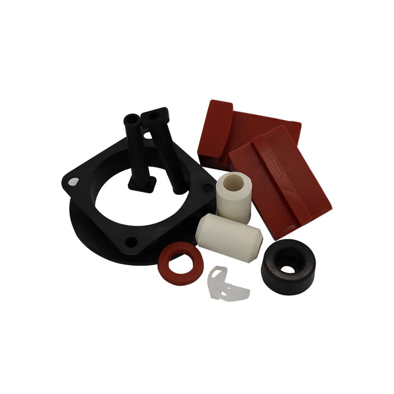
Design a Tear Trim That Breaks Predictably
A tear-trim groove creates a thin connection between part and overflow so excess can be removed. Its position, thickness, radius, and access must suit the compound and section. Poor geometry can leave heavy rubber flash or tear into the component.
Keep the tear path away from high-strain and sealing zones. Validate removal on production-intent material because tear behavior changes with formulation and cure.
Plan Trim Access Around Inserts and Undercuts
Metal inserts, deep grooves, and re-entrant shapes can block knives, wheels, or deflashing media. Provide access and protect bonded edges. A trim tool should not scrape coating or start a separation. Rubber flash removal must be considered before the insert fixture and mold split are frozen.
The rubber molding process guide provides additional rubber-to-metal manufacturing context.
- Mark the permitted parting-line path.
- Define critical no-trim zones.
- Provide safe trim access.
- Separate rubber flash, mismatch, and surface-defect limits.
- Approve representative edge samples where appearance is subjective.
Write a Measurable Flash Requirement
Specify maximum extension, thickness, location, and whether loose fragments are permitted. Define the inspection method and any zone-specific limits. “Flash free” and “good workmanship” do not create a repeatable decision. A measurable rubber flash note allows supplier and customer to inspect the same condition.
Use different limits for sealing, cosmetic, hidden, and trimmed edges where risk differs.
Distinguish Flash From Mold Mismatch
Flash is excess material at the split; mismatch is a step between mold sections. They have different causes and functional effects. A low fin may be harmless while a step disrupts sealing or assembly. Inspect and specify them separately.
Datum strategy matters because a shifted insert or cavity can resemble heavy rubber flash in a casual visual check. Measure the underlying molded surfaces.
Control Compound and Cure Without Overpromising
Flow and tear behavior vary with compound, storage, preform, mold temperature, and cure. ASTM D2000, ASTM D2240, and ASTM D412 can support material controls, but they do not define acceptable rubber flash.
Use production samples to validate trim and edge quality. Record tool maintenance if the flash pattern changes.
Approve Edges With Functional Testing
Inspect sealing continuity, installation, flexing, bond edges, and any loose particles after trimming. A visually smooth cut can contain a notch that grows under strain. ASTM D624 supports tear comparison, while the finished feature confirms performance.
The custom molded rubber parts and rubber gasket design guide pages show custom molded parts and tolerance guidance. Include the proposed split and trim method in DFM approval.
Tool maintenance should include the split surfaces and trim features that control the edge. A dent, corrosion spot, or resin-like deposit on the mold can change the fin pattern suddenly. Photograph recurring locations and compare cavities rather than treating every trim variation as operator performance. If repair requires welding or polishing, remeasure functional cavity relationships before production approval.
Packaging inspection is relevant when a thin trimmed edge can fold, stick, or pick up loose particles. Define whether parts are washed, counted, bagged, or separated, and inspect after the complete packaging cycle. An edge accepted directly after trimming may arrive damaged if parts rub against inserts or are compressed in bulk.
When appearance matters, create approved boundary samples showing acceptable and unacceptable edge conditions under defined lighting. Samples should not replace dimensions where measurement is practical, but they help align judgment for color, slight feathering, or surface texture that is difficult to express with one number.
Edge inspection should occur after any washing, tumbling, or handling step that could detach residual fragments. Loose material can contaminate an assembly even when the molded surface itself is acceptable. Define cleanliness and particle restrictions separately from the geometric fin limit. When a trimmed edge enters a groove or slides past another part, run an assembly trial to confirm it does not shave or roll.
Tool-cavity identification is useful when a multi-cavity mold shows different boundary conditions. Keep samples separated and compare the same locations. A cavity-specific pattern may indicate local split wear or closure rather than a compound-wide issue, allowing focused maintenance instead of changing the entire process.
Include trim-tool condition and maintenance frequency in production records when edge quality is critical.
Frequently Asked Questions
Can molded parts have zero rubber flash?
A literal zero is not a practical manufacturing definition. Specify measurable extension, thickness, location, and functional restrictions.
Where should rubber flash be located?
Prefer nonfunctional, accessible areas away from sealing lips, sliding surfaces, high-strain flexures, and critical appearance zones.
What is the difference between flash and mismatch?
Flash is a fin of excess material at the split; mismatch is a step caused by mold-section offset. Control them separately.
Can cryogenic deflashing remove all flash?
It suits some compounds and geometries but can affect thin desired features. Validate the process on the actual part.
What should a rubber flash drawing note include?
Include permitted zones, maximum extension and thickness, loose-particle restrictions, mismatch limits, inspection method, and approved edge samples if needed.
Review Rubber Flash Before Tooling
Huadao can review custom molded rubber parts for mold split, tear trim, insert access, appearance zones, and inspection.
Send the drawing through the contact page to place rubber flash where it can be controlled.