A drawing can be dimensionally complete and still be difficult to manufacture. This happens frequently when metal-part conventions are copied onto UHMWPE, nylon, POM, PTFE, or another engineering polymer. Tight plastic tolerances may conflict with thermal movement, moisture uptake, residual stress, part flexibility, or the way a soft surface is measured.
This guide helps OEM engineers prepare CNC plastic drawings and RFQs that protect function without adding unnecessary cost or inspection disagreement. It explains how to assign datums, identify critical fits, choose a measurement state, and discuss plastic tolerances with a machining supplier before production.
Table of Contents
Classify Plastic Tolerances by What They Control
Begin by marking dimensions that control assembly, motion, sealing, alignment, or safety. A bearing bore, mounting pattern, guide height, and overall cosmetic edge do not carry equal risk. When every dimension has the same narrow limit, the machinist cannot tell where process control matters most. Functional classification makes plastic tolerances easier to inspect and easier to quote.
For each critical feature, write the consequence of being high, low, or out of position. That short exercise often reveals that a profile tolerance, true position, or installed clearance is more appropriate than several independent plus/minus dimensions. It also exposes requirements that belong to the mating assembly rather than the polymer part alone.
Build a Stable Datum System for Plastic Tolerances
Choose datums that reflect how the component is located in the machine and how it can be held during machining and inspection. A thin flexible sheet may not have a naturally stable free-state plane. If the assembly clamps it flat, define whether measurement occurs restrained and describe the fixture. Otherwise, free-state plastic tolerances and installed function may be judged by incompatible setups.
Avoid long datum chains from rough stock edges or nonfunctional surfaces. A primary mounting face, a locating bore, and a clocking feature often create a more repeatable system. Include a datum-target scheme when only specific pads contact the assembly. The CNC plastic parts DFM guide provides related design-for-machining considerations.
| Drawing choice | Common problem | Better question |
|---|---|---|
| All dimensions ±0.05 mm | Cost rises without functional priority | Which features control fit or motion? |
| Large flexible face as datum | Part rocks or deflects during inspection | How is it constrained in service? |
| Edge-to-edge chain dimensions | Tolerance stack obscures hole location | Can holes use position from functional datums? |
| Surface finish on every face | Extra operations with little benefit | Which faces seal, slide, or locate? |
Account for Temperature in Plastic Tolerances
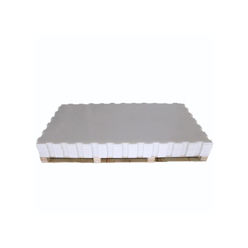
Engineering plastics generally move more with temperature than metals. A long UHMWPE wear strip measured in a cool inspection room can be noticeably different on a warm conveyor. Record the reference temperature for critical dimensions and calculate the potential change over the service range using data for the exact grade. Plastic tolerances should leave room for thermal movement unless the design deliberately restrains it.
Do not convert a calculated expansion directly into a guaranteed field dimension without considering anisotropy, stress, moisture, and mounting. Slots, floating fasteners, shorter segments, and expansion gaps can be more robust than attempting to machine a long polymer component to a metal-like room-temperature limit.
Treat Moisture-Sensitive Materials Separately
Nylon can change dimensions as it absorbs moisture, whereas POM, UHMWPE, and other plastics have different environmental responses. Specify material condition, conditioning method, storage, and time between unpacking and inspection when humidity affects fit. The POM CNC turning guide explains why nylon measurement state must be explicit.
For close-running parts, combine moisture movement with shaft, housing, temperature, and alignment variation. A bore that passes dry inspection can bind after conditioning, while excessive allowance may create noise when dry. Good plastic tolerances describe a workable operating window rather than a single ideal laboratory state.
- Name the exact polymer grade and reinforcement.
- State the inspection temperature and conditioning state.
- Define whether flexible parts are measured free or restrained.
- Separate critical fit dimensions from general dimensions.
- Provide mating-part limits for clearance and press-fit reviews.
Plan Plastic Tolerances Around Residual Stress
Extruded and molded stock may contain residual stress. Removing material heavily from one side, opening a large pocket, or boring a thick wall can release that stress and change flatness or roundness. Roughing both sides, allowing stabilization, and finishing functional surfaces later can improve repeatability, but the sequence adds time. Plastic tolerances should reflect whether that process is justified by function.
Material certification does not guarantee stress-free stock. Discuss stock form, oversize allowance, annealed material availability, and whether a first-piece trial is needed. Thin walls should include enough support for cutting and inspection; sometimes a small geometry change does more for stability than a tighter machining instruction.
Set Plastic Tolerances for Holes, Threads, and Fits
Small drilled holes can close slightly after machining, long bores can taper, and threads may deform under assembly torque. State whether a hole is for free passage, precision location, fluid flow, or tapping. Use inserts when repeated fastening or high thread load exceeds what the polymer can support. Plastic tolerances on threads should include the mating fastener and expected installation method.
For press fits, distinguish the free outside diameter from the installed bore or feature. Polymer creep, temperature, moisture, housing stiffness, and insertion damage all affect retention. Prototype the interface instead of applying a metal interference rule. ASTM D638 and ASTM D790 can support material comparison, but they do not calculate the finished press fit.
Define Surface Finish Only Where It Works
A roughness value can matter on a sealing land, bearing surface, optical path, or low-friction guide. On a noncontact face, it may add machining time without functional benefit. Identify the direction of motion and whether tool marks can carry fluid or debris across a seal. Use a representative surface sample when appearance matters more than a numerical roughness value.
Measurement method must suit the polymer. Soft or textured surfaces may not correlate well with a stylus result taken using metal assumptions. State whether the surface will be machined, molded, or finished after assembly. Practical plastic tolerances include edge-break and burr requirements at interfaces where loose chips could contaminate equipment.
Document Plastic Tolerances in the RFQ
Send the controlled 2D drawing and matching 3D model, then flag the dimensions that cannot change. Include annual volume, prototype quantity, mating components, service temperature, moisture, load, wear, and inspection expectations. Ask the supplier to identify tolerance, workholding, stock, and measurement risks before quotation is finalized.
Use ASTM D543 for controlled chemical-resistance comparison and ASTM D648 when heat-deflection data is relevant, but avoid filling the drawing with unrelated tests. The custom CNC machined plastic parts page shows the range of custom CNC components for which focused plastic tolerances and application details support a clearer review.
Frequently Asked Questions
Can plastic tolerances match metal-part limits?
Some small, stable features can, but capability depends on material, size, geometry, temperature, conditioning, workholding, and inspection. The important question is whether the tolerance remains meaningful in service.
Which materials support stable plastic tolerances?
There is no universal answer. POM is often considered for precision components, while filled grades can reduce movement in certain directions. Chemical exposure, temperature, moisture, wear, and geometry still govern selection.
How are plastic tolerances measured on flexible sheet?
State whether it is measured free-state or restrained on a defined fixture. If the assembly clamps it flat, a restrained profile requirement may represent function better than unsupported flatness.
Should general plastic tolerances apply to every feature?
No. Use general limits for noncritical geometry and place explicit controls on dimensions that affect fit, motion, sealing, alignment, or inspection. This communicates priority to the manufacturer.
What files define plastic tolerances for an RFQ?
Provide a revision-controlled 2D drawing, matching 3D model, material grade, quantities, critical features, mating-part information, service environment, measurement state, and any first-article documentation required.
Request a CNC Plastic Tolerance Review
Huadao can review custom CNC machined plastic parts for datum strategy, stock form, workholding, wall stability, fit allowance, surface requirements, and inspection method. DFM feedback is most effective before every limit is frozen.
Send the drawing package and application conditions through the contact page to discuss plastic tolerances that protect assembly function and remain practical for repeat production.