A low-friction sheet can improve flow in one chute and fail rapidly in another because impact, sliding, temperature, seams, support, and fastening are different. Selecting a wear liner by polymer name alone overlooks the mechanism that removes material and the structure that holds the sheet in place.
This guide helps bulk-material teams choose and install a UHMWPE wear liner for chutes and hoppers while comparing impact, abrasion, flow, expansion, fasteners, seams, and replacement access.
Table of Contents
Map Impact and Sliding Zones Separately
Mark where material first strikes, changes direction, accelerates, and settles into sliding. Direct impact can gouge or deform a wear liner, while long sliding distance produces another wear pattern. Use particle size, shape, drop height, velocity, angle, and throughput to define zones.
Do not assume one thickness or material should cover the entire chute. An impact zone may need a different system from a low-angle flow surface.
Identify the Flow Problem Before Choosing UHMWPE
If the objective is to reduce sticking, document moisture, fines, temperature, wall angle, outlet size, and where buildup starts. Low friction helps only when geometry and consolidation allow movement. A wear liner cannot correct an undersized outlet or unstable bulk-flow design by itself.
Record whether buildup occurs during running, shutdown, freezing, or cleaning. These conditions affect seams and drainage.
| Zone condition | Possible liner direction | Main verification |
|---|---|---|
| High direct impact | Impact-tolerant or sacrificial system | Backing support and gouging |
| Long abrasive slide | UHMWPE or wear-focused surface | Thickness loss pattern |
| Sticky low-speed fines | Low-friction lining | Flow and buildup trial |
| High temperature | Temperature-suitable alternative | Property retention and expansion |
| Sharp hot material | Metal or layered system review | Cutting and heat resistance |
Choose Thickness With Backing Support
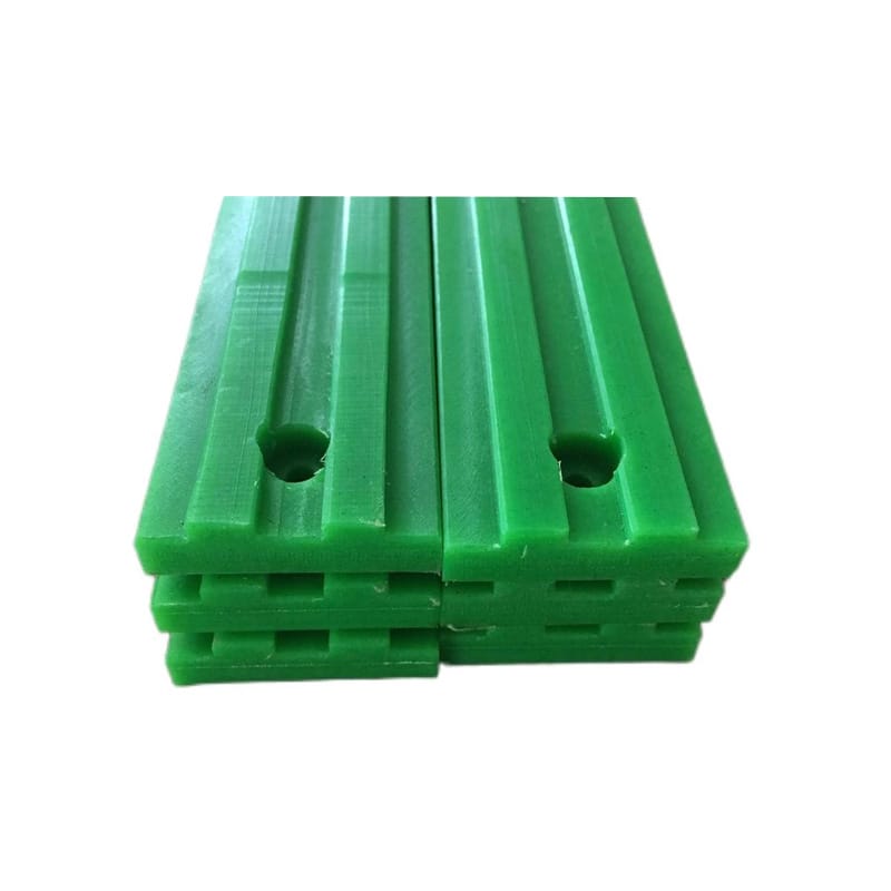
Thickness affects wear allowance, fastener recess, stiffness, weight, and cost, but unsupported sheet can flex and pull at fasteners. Inspect the structural wall and repair high spots, holes, and corrosion. A wear liner needs continuous or deliberately spaced support appropriate to load.
Avoid using liner sheet as structural reinforcement. The chute must carry operational loads independently.
Lay Out Seams With Material Flow
Place seams so material does not catch an upstream edge. Use lapped, scarfed, stepped, or tightly aligned joints as appropriate. Keep seams away from peak impact and concentrated flow where practical. A proud wear liner edge can start peeling and collect material.
Stagger joints when several panels would otherwise create a continuous cross-flow ridge.
- Map impact and sliding before panel layout.
- Orient seams with flow.
- Recess fasteners below the wear liner surface.
- Allow thermal movement.
- Provide safe replacement access.
Allow Thermal Expansion Without Buckling
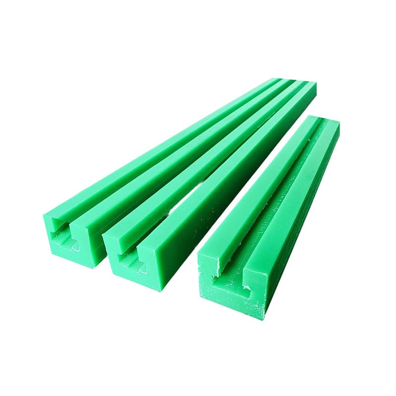
UHMWPE moves substantially with temperature. Use a defined locating point, slotted holes, suitable washers, and expansion gaps based on panel length and credible temperature. A rigidly clamped wear liner can buckle into the flow or load fasteners.
Check cold gaps and hot closure. Ensure movement does not expose a catching edge.
Design Fasteners for Wear and Inspection
Countersunk heads should remain below the working surface through the planned replacement thickness. Hole geometry must leave enough material around the fastener and allow movement where intended. Inspect torque and backing condition. A loose fastener can damage both wear liner and conveyed product.
Use hardware compatible with moisture and chemicals, and prevent hidden protrusions outside the chute.
Compare Materials Against the Actual Mechanism
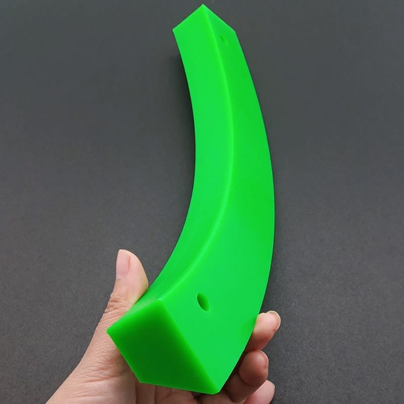
UHMWPE, HDPE, polyurethane, metal wear plate, ceramics, and layered systems offer different balances of friction, impact, cutting, heat, noise, and installation. Use ASTM D638, ASTM D790, ASTM D256, and ASTM D648 as material evidence where relevant.
No coupon result predicts a complete wear liner life under mixed impact and sliding.
Track Wear by Chute Zone
Create fixed measurement points, baseline thickness, photographs, seam condition, fastener condition, and inspection intervals. Trend high-impact and high-slide zones separately. Replace before fasteners or structure enter the wear path.
The machined plastic wear parts, UHMWPE wear parts maintenance guide, and UHMWPE wear strip selection guide provide related wear-part information. Use the map to refine the next wear liner layout.
Installation sequence should start at the chosen locating zone and progress in a way that preserves flow alignment. Trial-fit panels, verify seams, and mark slot centers before final fastening. For overhead or confined work, the method must also protect workers and prevent loose hardware or panel sections from entering the chute. Follow the site’s isolation and access procedure throughout.
Buildup behind panels can force them away from the wall and increase local fastener load. Seal or design joints according to the process requirement while providing drainage and inspection. If fine material repeatedly enters one edge, investigate the upstream transition rather than adding more fasteners without understanding the path.
A replacement plan can use zone-specific thickness readings, photographs, seam condition, and exposed fastener depth. Record conveyed material changes because a new sharp or hot fraction can alter wear rapidly. Retaining one removed panel with its location marked supports comparison with future wear liner selections.
Impact shields or sacrificial panels may be used upstream of the low-friction surface when large particles strike directly. Their attachment and replacement must not create protrusions that redirect flow into adjacent sheets. Compare a layered arrangement with a single thicker panel by examining support, joint height, maintenance access, and how each component fails.
Temperature should be checked at the wall and conveyed material, not estimated from ambient air. Friction, hot product, steam cleaning, sunlight, or nearby equipment can create local peaks. If the polymer approaches a condition where stiffness or strength changes materially, evaluate another grade or system rather than relying on additional fasteners.
During shutdown, inspect behind accessible sample panels for trapped fines, moisture, corrosion, and elongated holes. Hidden conditions can explain buckling or loose edges before front-surface thickness is exhausted. Use this information to refine sealing, drainage, and support on the next maintenance cycle.
Keep installation templates and hole data under revision control so replacement panels align with existing structure without on-site drilling that leaves rough, misplaced, or unsupported fastener locations.
Frequently Asked Questions
How thick should a UHMWPE wear liner be?
Thickness depends on wear mechanism, expected allowance, support, impact, fastener recess, panel size, temperature, and replacement plan.
Can a wear liner stop chute blockage?
It may reduce wall friction, but outlet size, wall angle, consolidation, moisture, fines, and geometry still govern flow.
Why does a wear liner buckle?
Common causes include rigid fastening, insufficient expansion gaps, uneven support, temperature movement, and poorly placed locating points.
Where should wear liner seams be placed?
Orient them with flow, keep downstream edges flush, and avoid peak impact or concentrated flow where practical.
What data is needed for wear liner selection?
Provide chute drawings, material size and shape, drop and impact, flow path, temperature, moisture, chemicals, current wear map, support, access, and replacement history.
Request a Wear Liner Layout Review
Huadao can review machined plastic wear parts for zones, panel layout, seams, expansion, support, and fastening.
Share the chute drawing through the contact page to select a wear liner around the actual wear mechanism.