UHMWPE can provide a low-friction running surface, but a good polymer cannot correct a twisted support, trapped debris, rigid thermal restraint, or a chain entering at the wrong height. Most premature wear strip problems begin at installation interfaces rather than in the middle of a straight section.
This field guide explains how to install and align a conveyor wear strip so chain load is distributed, expansion is permitted, fasteners remain protected, and joints do not become impact points.
Table of Contents
Survey the Conveyor Before Installing Wear Strip
Check frame straightness, support elevation, bracket spacing, chain path, sprocket position, and existing wear marks. Establish a centerline and reference height rather than following a distorted old wear strip.
Correct loose brackets, sharp welds, and contamination first. Photograph curves, transfer points, and high-load zones. The installation drawing should state which point locates the profile and which points are allowed to float.
Prepare a Continuous Support Surface
UHMWPE conforms under load. Gaps or high spots concentrate pressure and print through to the chain path. Deburr supports and verify flatness with the method appropriate to the conveyor length. A wear strip should not bridge a large unsupported span unless designed to do so.
Provide drainage and debris escape where washdown or fines occur. Material trapped underneath can lift the guide and create a local step.
| Installation issue | Likely symptom | Correction |
|---|---|---|
| High support point | Localized rapid wear | Level or shim support |
| Both ends fixed | Buckling when warm | Use one locating point and expansion slots |
| Joint step | Chain impact and noise | Align ends and use a suitable transition |
| Proud fastener | Chain and hardware wear | Recess outside the wear path |
| Misaligned curve | Edge loading | Set tangent and entry geometry |
Allow Wear Strip Thermal Expansion
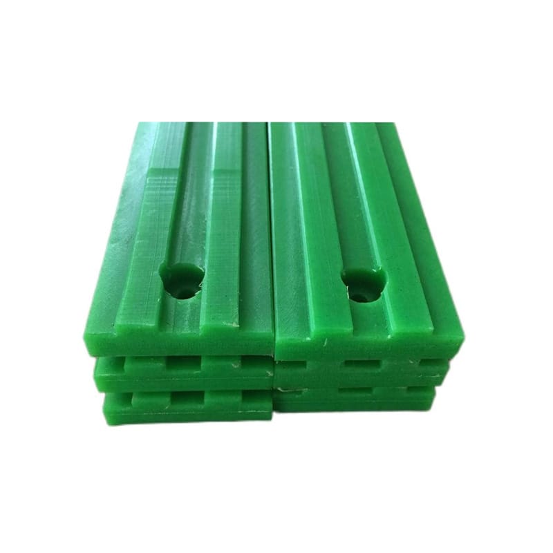
Long UHMWPE sections can change length substantially with temperature. Locate the wear strip at a defined point and use slots, clips, or other approved floating attachment elsewhere. Expansion allowance must reflect section length, grade, operating range, and frame temperature.
Do not clamp both ends rigidly and then expect fastener slots to work. Washers, torque, and slot orientation must permit sliding. Keep expansion gaps from becoming sharp chain-impact edges.
Design Joints in the Direction of Travel
Place joints away from the highest load or transfer impact where practical. Align the running surfaces and use a scarfed, stepped, or manufacturer-approved transition when the chain would otherwise strike a square edge. The downstream end of a wear strip must not stand proud.
Stagger joints on parallel tracks when simultaneous impact could disturb product. Check joint condition at cold and hot limits because expansion changes the gap.
- Mark chain travel before cutting.
- Deburr every wear strip joint and entry.
- Keep fasteners below the running surface.
- Provide the calculated expansion gap.
- Verify support spacing at curves and loads.
Align Straight Runs and Curves
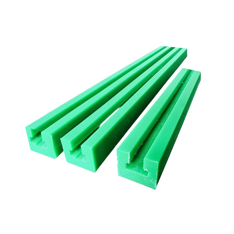
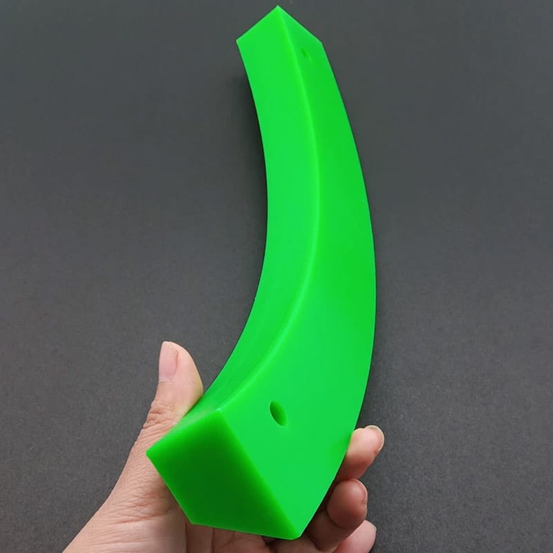
Use a taut reference, laser, fixture, or controlled mechanical method suited to the conveyor. Measure lateral offset and height at defined intervals. A chain forced sideways into a curve creates edge wear and heat. The wear strip entry should be tangent and smooth.
For machined tracks, inspect curve radius and channel width against the actual chain. Account for chain articulation and wear, not just nominal catalog dimensions.
Protect Fasteners From the Wear Path
Countersinks must retain sufficient polymer under the head and avoid sharp cracks. Fastener spacing should hold the wear strip flat without preventing expansion. Use hardware compatible with washdown, frame material, and maintenance procedure.
A fastener should not become the primary rubbing surface as the guide wears. Define replacement thickness or inspection markers before the chain can contact metal.
Check Chain Condition and Lubrication
A seized link, sharp side plate, stretched chain, misaligned sprocket, or unsuitable lubricant can damage a new guide quickly. Inspect chain pitch, articulation, tracking, and tension before startup. Wear strip replacement should not be used to hide a transmission fault.
Review chemical compatibility using ASTM D543 where relevant. ASTM D638, ASTM D790, and ASTM D648 support material comparison but not installed alignment.
Commission and Inspect the Wear Strip
Turn or jog the conveyor using the approved procedure and observe entry, curves, transfers, noise, and chain tracking. After a short controlled run, inspect contact marks and temperature. Early localized polish reveals alignment before severe wear strip damage occurs.
The UHMWPE conveyor wear strip, UHMWPE wear strip selection guide, and UHMWPE wear parts maintenance guide pages provide related product and selection information. Record final alignment, gaps, fasteners, and baseline photographs.
Support spacing should be reviewed where product or chain load changes. A guide that remains straight on an empty conveyor can deflect under accumulated product, side pressure, or a jam. Measure the installed track under representative load where feasible. At transfer points, check that the moving element cannot climb the profile or strike a fastener during tension variation. Structural brackets should carry the load; the polymer provides the running interface.
Washdown design needs more than chemical compatibility. Trapped water can carry fines beneath the profile, corrode hardware, freeze, or prevent the guide from sliding in its slots. Provide drainage and make inspection possible without dismantling an entire run. After cleaning, confirm that no loose debris remains at joints or curves.
Create a replacement rule based on remaining profile, fastener cover, joint condition, chain tracking, and heat rather than elapsed time alone. Measure at fixed stations and retain baseline readings. A predictable trend allows sections to be changed before metal contact while avoiding premature replacement of lightly loaded zones.
At accumulation zones, side pressure can be much higher than the normal conveying load. Inspect whether product backs up against rails, curves, or transfers and whether the guide is being used as a structural stop. If so, correct controls or add an engineered load path rather than increasing polymer thickness without calculation. The running profile should guide motion while brackets and frame carry the imposed force.
Before final handover, create an as-installed sketch showing locating points, slot directions, cold gaps, joint orientation, fastener type, and baseline measurements. Future maintenance can then distinguish intended movement from loosening or damage. This record is especially useful when sections are replaced at different times or when seasonal temperature changes alter visible gaps.
Spare sections should be stored flat or supported according to profile so they do not take a permanent bend before installation. Keep them away from heat and incompatible chemicals, and preserve identification for grade and drawing revision. Before fitting an older spare, compare its straightness and dimensions with the current controlled requirement.
Frequently Asked Questions
How much expansion gap does a wear strip need?
Calculate it from material grade, free length, and credible temperature range, then account for the chosen locating and floating attachment method.
Should both ends of a wear strip be fixed?
Usually not for a long thermally moving section. Use a defined locating point and allow controlled movement elsewhere.
Why does a wear strip wear at one edge?
Check chain and sprocket alignment, curve tangent, support height, frame distortion, and lateral load before changing material.
Can fasteners sit in the chain path?
They should remain protected below the running surface through the intended replacement point.
What should be checked after installation?
Verify alignment, joint height, expansion gaps, fastener seating, chain condition, noise, tracking, temperature, and early contact marks.
Review a Conveyor Wear Strip Layout
Huadao can review UHMWPE conveyor wear strip for profile, curves, support, joints, expansion, and fastening.
Send the conveyor layout through the contact page to align the wear strip with the actual chain path.